Start Stop Motor Control Wiring Diagram
Common Electrical Motor Controlled Circuit 1
Https Www Mikeholt Com Instructor2 Img Product Pdf 1245861713sample Pdf

Control Circuits Schematic Diagrams Wiring Diagrams And Reading
Starting stopping of 3 phase motor from more than one place power control diagrams whenever we need to start and stop the motor from more than one point then we may expand it through push buttons in the motor control circuit for example you may use this alternative power control wiring diagram of controlling a three phase motor from mo re than two places.

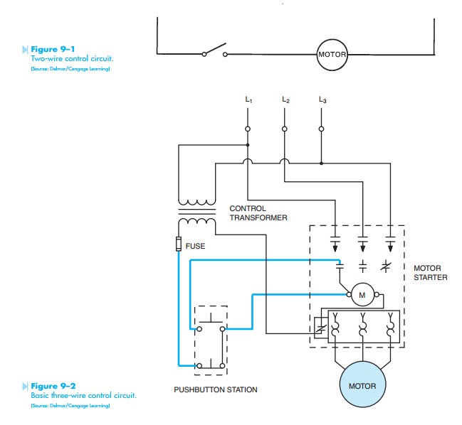
Start stop motor control wiring diagram. M a1 a2 m. This diagram is for 3 phase reversing motor control with 24 vdc control voltage. Typical wiring diagrams for push button control stations 7 start stop control wiring diagrams single station with motor stopped pilot light l1 start l2 i 1 stop 2 oi 3 n wol. Ladder diagram basics 3c 3 wire control duration.
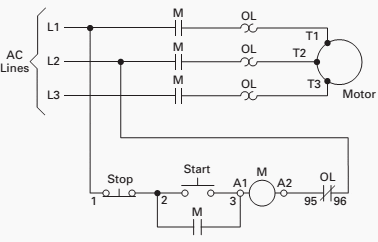
Pilot light l2 4 2 3 pilot light start stop bulletin 1495 normally closed auxiliary contacts are required. T w 6. This video builds on the standard 3 wire circuit by incorporating multiple stopstart. Control wiring 3 wire control start stop circuit the most common use of 3 wire control is a startstop control.
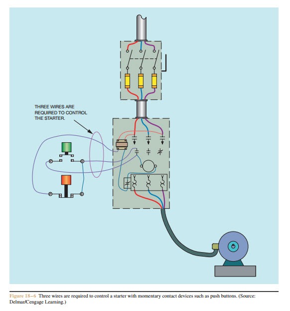
6 mike holts illustrated guide to understanding basic motor controls unit 1 basic principles of motor controls different manufacturers of control devices as well as books about motor controls use different methods of showing the control circuit wiring. See image below for an example of 3 wire control being used to pull in a contactor to start a 3 phase motor. With the switch closed the control circuit acts as a normal stopstart station controlling a load connected to the pilot device power is sitting on the start and seal in terminals of the pushbutton. This video guides you how the stopstart motor control circuits wiring done.
A three wire control circuit uses momentary contact startstop stations and a normally open seal in contact connected in parallel with the start button to maintain voltage to the coil. 3 wire start stop. Theres a diagram shown in the process. The basic operation of the stopstart circuit is to provide a means of remotely controlling a motor operated load from a panel that only contains the low voltage control circuitry.
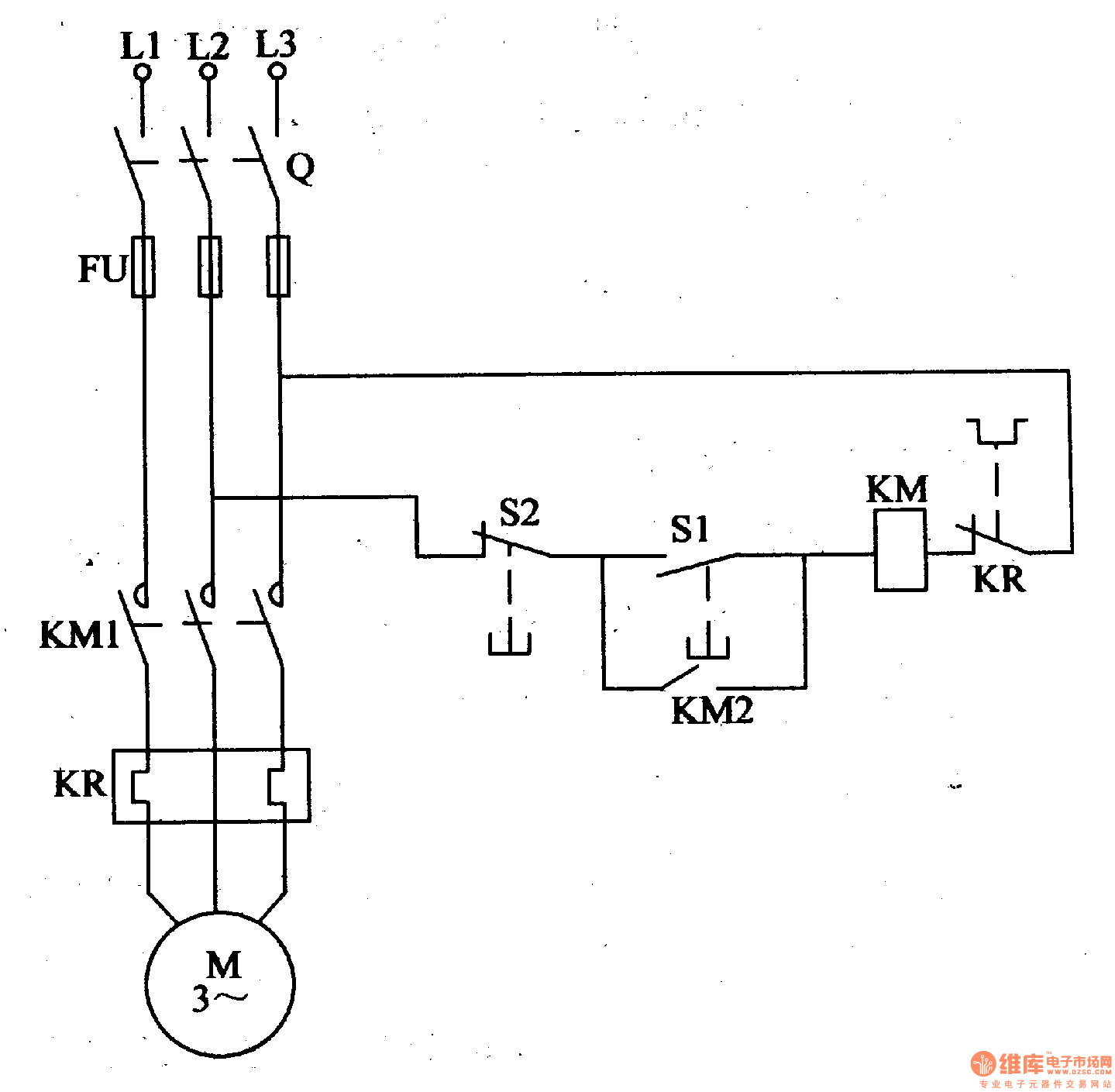
For example in figure 13b1 the control wiring from the start stop. Motor control circuits are effective way to reduce cost by using smaller wire. It uses two contactors two auxiliary contact blocks an overload relay a mechanical interlock two normally open start pushbuttons a normally closed stop pushbutton and a power supply with a fuse. C i m nc.
Fiber optic cable electrical connections motor 3ct to v separate control ot is a switch that opens when an overtemperature condition exists type mfo and mgo only t1 t3 wiring diagram.

Tk 9826 Wiring Diagram Together With Start Stop Motor Control
Basic Wiring For Motor Control Technical Data Guide Eep
3 Phase Wiring Question Start Stop Switch The Home Machinist
Basic Control Circuits Three Wire Control Circuits Electric

Motors Motor Circuits And Controllers Part V Article 430

Practical Machinist Largest Manufacturing Technology Forum On

Contactor Wiring Diagram Lair Dego7 Vdstappen Loonen Nl
Control Circuits Schematics And Wiring Diagrams Hvac Machinery
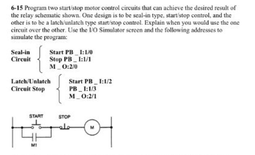
6 15 Program Two Start Stop Motor Control Circuits Chegg Com
