Single Phase Motor Control Diagram With Timer

Star Delta Starters Explained The Engineering Mindset
Electric Motors Symbols Ac Dc Single Phase Three Phase Motors
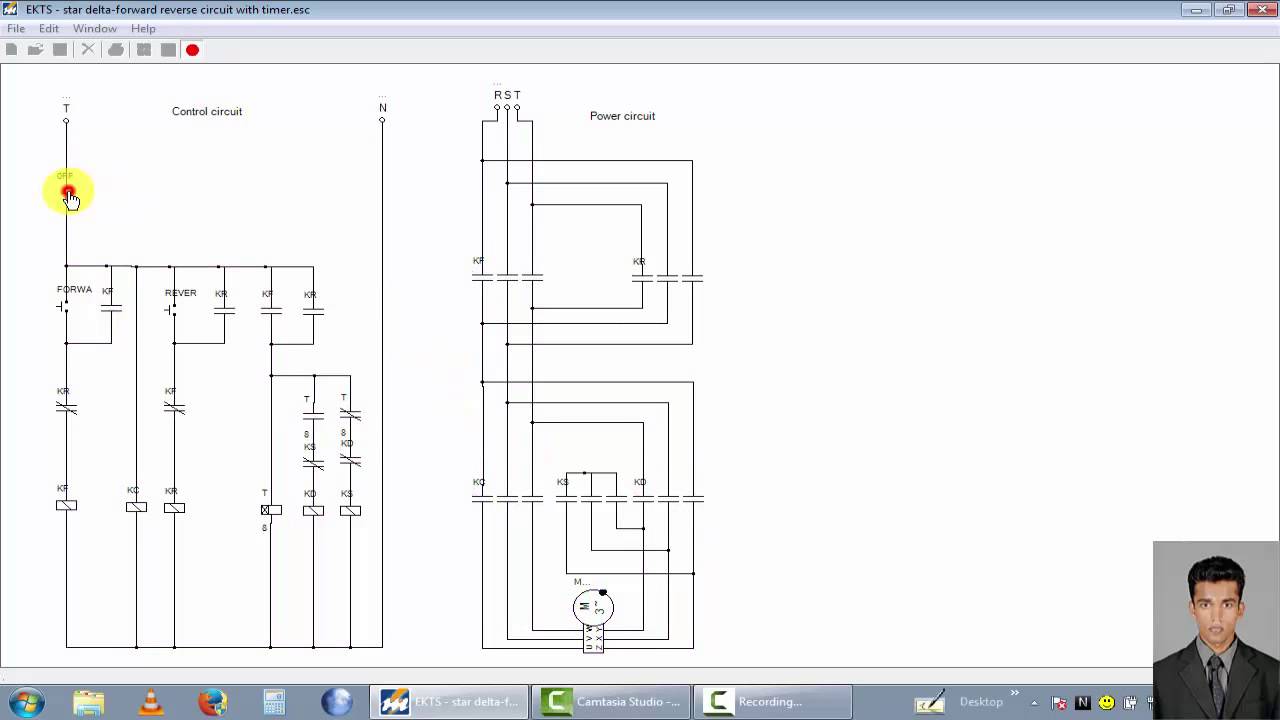
Three Phase Motor Control Circuit Star Delta Forward Reverse
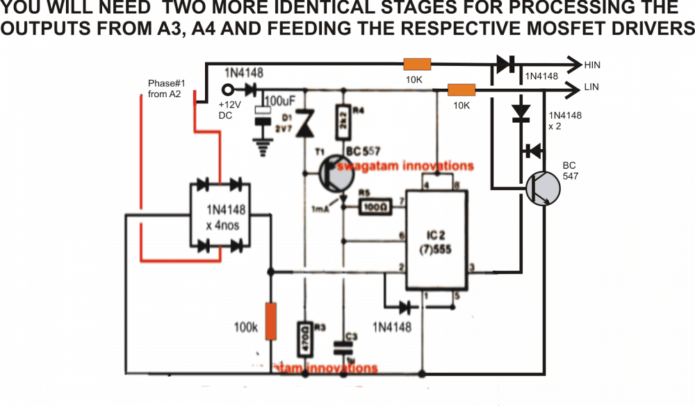
In this scenario the microcontroller should be reprogrammed to output sine voltages with 120 degree phase shift to each other which drives a three phase induction motor.
Single phase motor control diagram with timer. It reveals the components of the circuit as simplified forms as well as the power as well as signal links in between the tools. Variety of single phase motor wiring diagram forward reverse. In many cases the single phase motors on board a. The motor driver utilizes the core independent peripheral cip in the microcontroller to perform motor control function with minimum interven tion from its central processing unit cpu.
A single phase induction motor consists of a single phase winding on the stator and a cage winding on the rotor. Schematic diagrams for the single phase motors. For most shore facility applications this is the case. In a low power motor application where cost is more important than complexity and torque requirements are reduced a single phase brushless dc bldc motor is a good alternative to a three phase motor.
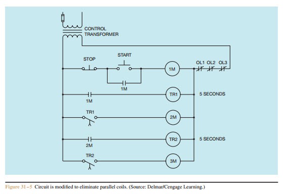
In this video we explain motor start stop with on delay off delay timer by using this controlling we can control our single phase and three phase with timer that means if we wants to stop our. The basic diagram view a shows a circle with two leads labeled t1 and t2. This type of motor is low cost because of its simple construction which is easier to fabricate. Block diagram figure 1 shows the block diagram of a single phase bldc motor driver based on the pic16f1618 microcontroller.
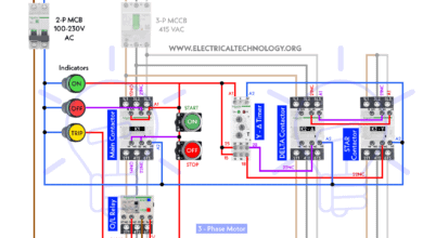
Also it only requires a single position sensor and a. The benefits of single phase bldc motors. The above diagram is a complete method of single phase motor wiring with circuit breaker and contactor. A wiring diagram is a simplified conventional pictorial representation of an electrical circuit.
One line diagram of simple contactor circuit control onoff circuit diagram of typical electrically held lightingheating contactor a contactor is an electr. Another advantage of using the three phase control method is that the same drive hardware topology can be used to control a three phase induction motor. The key to understanding the purpose of an overload heater is found by examining the single phase l1 l2 control circuit where a normally closed switch contact by the same name oel is connected in series with the motor relay coil. These are the cips used in the design.

Motor Control Circuits Types Electrical Industrial
Sequence Control Automatic Sequence Control Electric Equipment

3 Phase Motor Reversing With Delay And Limit Switches

On Delay Timer Relay Circuit Quotes Wiring Schematic Diagram 9

Industrial Control Basics Part 1 Contactors C3controls
Index 1585 Circuit Diagram Seekic Com

220v Single Phase Motor Wiring Diagram Single Motor Connection

Direct On Line Starter Electrical Notes Articles

How To Install 3 Phase Timer
