Motor Control Panel Wiring Diagram Pdf
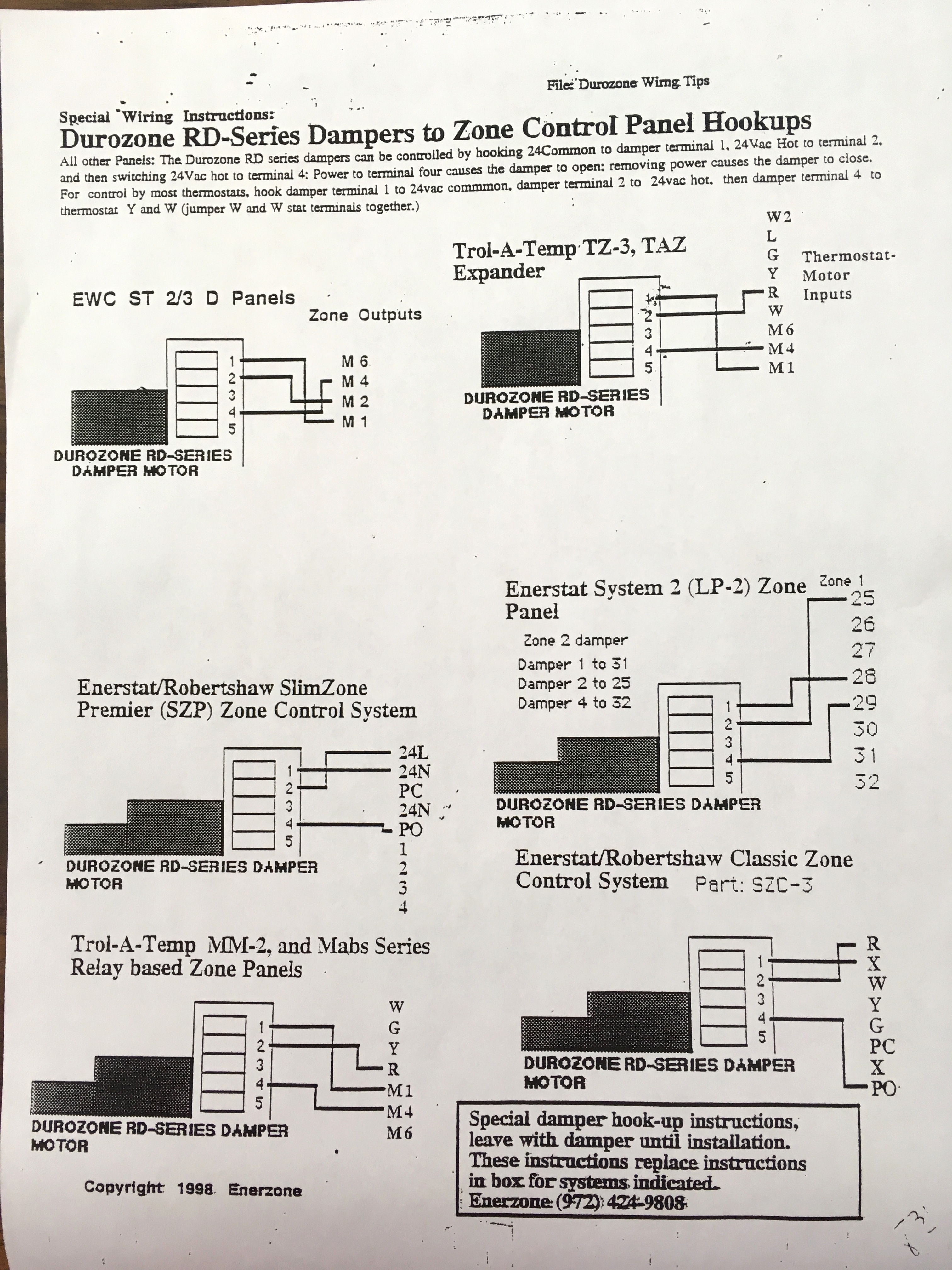
Damper Wiring Diagram Wiring Library
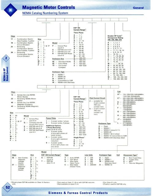
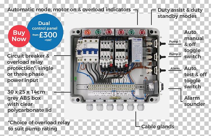
Download The Catalog Data Sheet Pdf Livewire Electrical Supply

59c Motor Control Wiring Diagram Pdf Wiring Resources
Motor control circuits motor control circuits are an effective way to reduce cost by using smaller wire and reduced amperage.

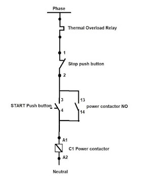
Motor control panel wiring diagram pdf. Typical wiring diagram covers most basic gate automation installations including photocells. The contacts m will be controlled by the coil mthe output of the motor starter goes to a three phase ac motor. Figure 1 a motor controller schematic. All about motors motor protection eaton wiring manual 0611 8 4 8 8 overload relay with reclosing lockout they should always be used where continuous contact devices two wire control are concerned eg.
Electric motor drawing at getdrawings. This type of diagram is helpful when wiring the. The lower voltage is then used to supply power to the left and right rails of the ladder below. The reset button can be fitted as an external feature in order to make it.
A simple circuit diagram of contactor with three phase motor. Sel generator control panel wiring diagram genset controller. A line diagram gives the necessary informa tion for easily following the operation of the various. Electrical control panel wiring diagram pdf download diesel generator control panel wiring diagram.
Get adobe reader. A wiring diagram gives the necessary information for actually wiring up a group of control devices or for physically tracing wires when trouble shooting is necessary. Wiring diagram book a1 15 b1 b2 16 18 b3 a2 b1 b3 15 supply voltage 16 18 l m h 2 levels b2 l1 f u 1 460 v f u 2. Basic wiring for motor control technical data.
In this tutorial we will show the star delta y d 3 phase induction ac motor starting method by automatic star delta starter with timer with schematic power control and wiring diagram as well as how star delta starter works and their applications with advantages and disadvantages. Came zm3e control panel fitting instructions. Fine how to install electrical panel board inspiration best. Up tp 93 off.
Unit 1 basic principles of motor controls unit 1introduction this unit discusses the basic concepts of motor control including motor control language and the types of wiring diagrams used. Motor 3ct to 120 v separate control ot is a switch that opens when an overtemperature condition exists. You may also read. Pressure and position switches to prevent automatic restarting.
Wiring diagrams show the connections to the controller. Came frog motor fitting instructions. Wiring diagrams sometimes called main or construction diagrams show the actual connection points for the wires to the components and terminals of the controller. Came zl150n control panel fitting instructions.
Simple Two Speed Contactor Dc Motor Controller
Star Delta Starter Working Principle Theory Circuit Diagram
Wiring Diagrams For Motor Circuits Lair Kobe Klictravel Nl

Ge 4 Pole Contactor Control Diagram Diagram Base Website Control

Dol Starter Direct Online Starter Diagram Working Principle
Electrical Control Panel Wiring Diagram Om Aceh Tintenglueck De

59c Motor Control Wiring Diagram Pdf Wiring Resources

Fl 3648 Star Delta Control Wiring Diagram Pdf Schematic Wiring
The Basics Of Motor Control Centers Mccs Eep
