Lathe Gearbox Diagram
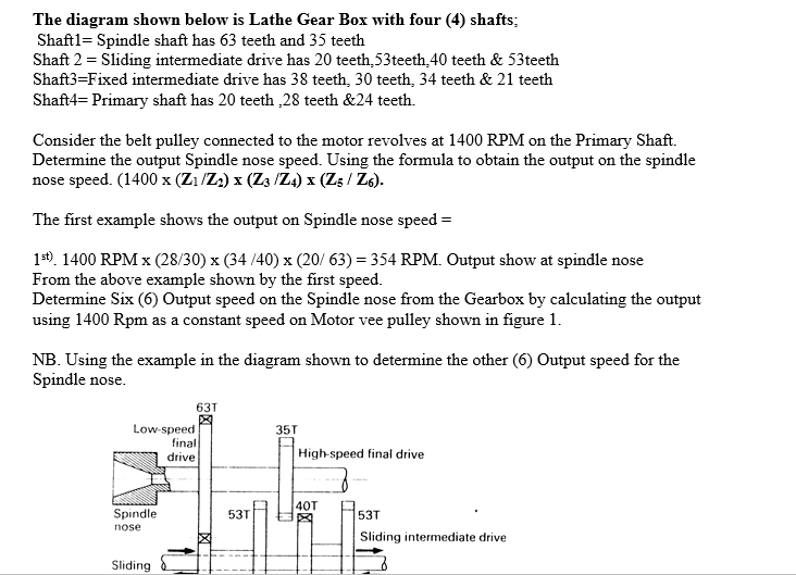
The Diagram Shown Below Is Lathe Gear Box With Fou Chegg Com

Logan 200 Assembly Drawings

Lathe
The range of speeds should be from 600 to 23 rpm respectively.

Lathe gearbox diagram. A lathe is a machine tool which is used to rotate a workpiece to perform various operations such as turning facing knurling grooving etc with the help of tools that are applied to the workpiece. The use of gears in most of the equipment gives you control over torque speed and synchronisation and their use in a lathe machine is no exception. Figure 5 when the lathe is off oil should be visible at all times in the gearbox oil sight window. When you machine different materials even if the geometry of the job is similar you would gen.
Gears in the gearbox are splash lubricated from an oil tank that is part of the gearbox. It took a little over 10 years for a screwcutting and feeds gearbox to become available as an option for the atlas lathe but when it was introduced in 1947 it was also offered as complete conversion kit to for retro fitting to earlier lathe both those with 34 and 58 diameter leadscrews. 2700 series parts list pk126m key 5 x 5 x 32 2724 p04922724 shaft 2725 p8102 bearing 8102 2726 p04922726 flange hub g0492 12 x 36 combo lathemill part description 2727 psb24m cap screw m5 8 x 16 2728 p8102 bearing 8102 2729 p04922729. Number of steps rquired are 12 and drive is from a 3 kw motor running at 1440 rpm.
Clamped to the lathe ways it uses adjustable fingers to contact the workpiece and align it. Ngc io pcb troubleshooting guide. If the gearbox does not shift it may have internal damage. Machine shop tips 130 repairing a logan lathe gear box part 1 tubalcain duration.
Lathe gear box oil upgrade doubleboost. Quick change gearbox. If the gearbox shifts refer to these troubleshooting guides for the high and low gear solenoids and the io pcb. Controls the movement of the carriage using levers.
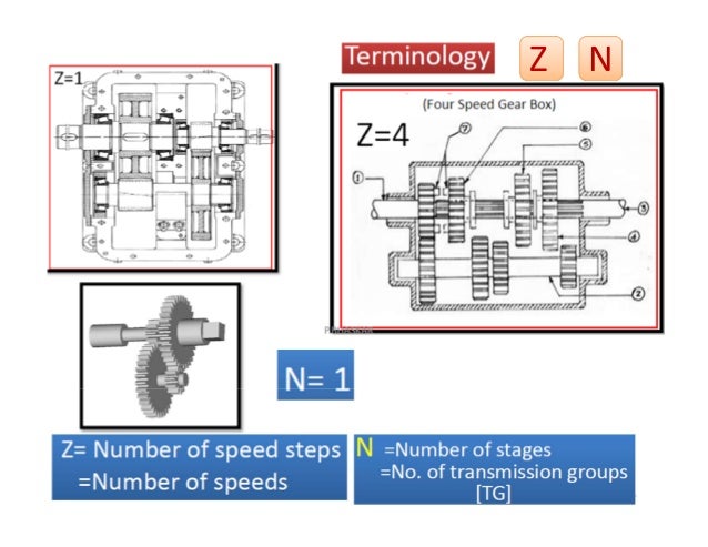
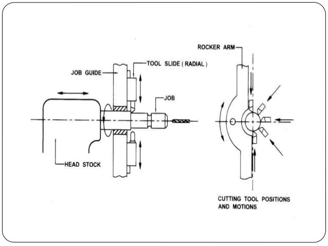
8 draw the ray diagram and kinematic layout of a gearbox for completely geared headstock of a lathe. Can be used in place of tailstock or in the middle to support long or unstable parts being machined. In this post we will discuss the lathe machine its main parts working principle operations advantages and disadvantages with diagram and video tutorial. The headstock is fixed on the machine and it consists of many pulleys lever spindle chuck and gear box.
The gearbox should shift and the hi gear and low gear bits on the diagnostic page should change state. The removal of material from metal is called machining and the process usually happens in a machine shop that has special equipment. An oil sight window is typically situated on the front or side face of the gearbox figure 5.
Machine Tool Gear Box

Updating The Ew Lathe Model Engineering Norge

Myford Ltd Home Page British Engineering At Its Best
Https Www Irjet Net Archives V5 I4 Irjet V5i4488 Pdf
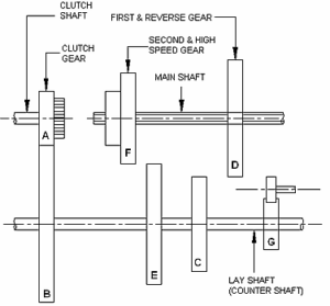
Sliding Mesh Gearbox Main Parts Working And Application

Myford Ltd Home Page British Engineering At Its Best
Lathe Machine

Harrison Gear Box Model Engineer
Voest Lathe
