Combination Motor Starter Wiring Diagram
Wiring Diagram For Schneider Dol Starter Wiring Schematic

Mb 4256 Dol Control Wiring Diagram Free Diagram
3c30 Combination Motor Starter Wiring Diagram Wiring Library
In north america an induction motor will typically operate at 230v or 460v 3 phase 60 hz and has a control voltage of 115 vac or 24 vdc.
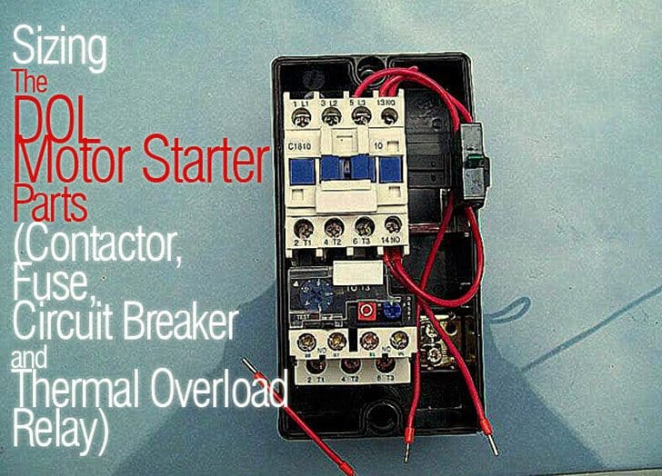
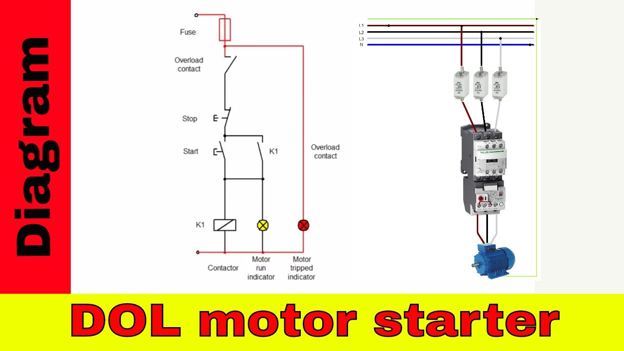
Combination motor starter wiring diagram. Motor starter schematic and wiring diagram. Collection of square d combination starter wiring diagram. A motor starter is a combination of devices used to start run and stop an ac induction motor based on commands from an operator or a controller. It reveals the elements of the circuit as streamlined shapes as well as the power as well as signal links between the tools.
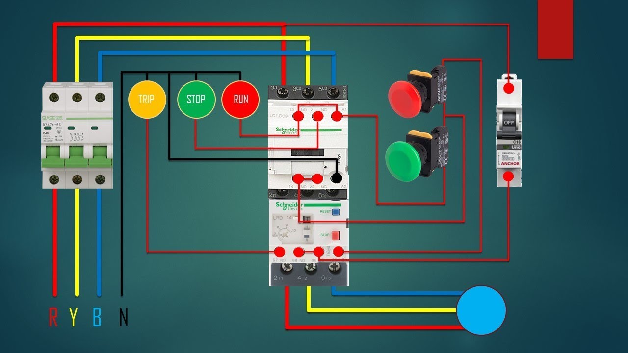
Square d size 1 starter wiring diagram magnetic motor definite. Wiring diagram will come with numerous easy to adhere to wiring diagram instructions. Wiring diagram book a1 15 b1 b2 16 18 b3 a2 b1 b3 15 supply voltage 16 18 l m h 2 levels b2 l1 f u 1 460 v f u 2. As long as you follow the ladder diagram and take it one wire at a time its simple.
Starting a three phase motor. Class 8538 combination starters are available in nema size 06. Allen bradley motor starter wiring diagram fresh fine allen bradley. How to wire a motor starter number.
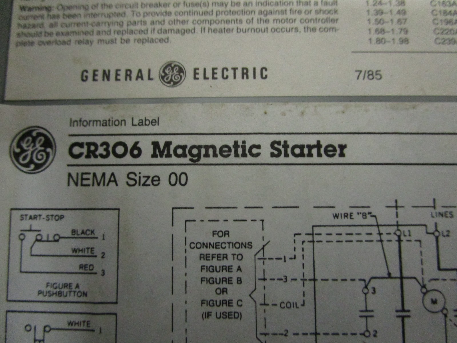
These instructions will be easy to understand and apply. A wiring diagram gives the necessary information for actually wiring up a group of control devices or for physically tracing wires when trouble shooting is necessary. Motor 3ct to 120 v separate control ot is a switch that opens. This video is a step by step explanation of wiring start stop basics.
Original a motor starter is a combination of devices to allow an induction motor to start run and stop according to commands by an operator or a controller. The wiring diagrams heavy lines. Square d magnetic motor starter wiring diagram elegant square d square d motor starters wiring diagram. Its supposed to help all the average person in building a correct system.
Typically an induction motor will run by a. A line diagram gives the necessary informa tion for easily following the operation of the various. Start stop 3 wire control. The design of the fusible disconnect switch combination starter uses a flange operated visible blade switch.
This is the first of many motor control. Square d combination starter wiring diagram gallery nice manual motor starter wiring diagram frieze electrical circuit. Wiring diagrams 55 57 type s ac combination magnetic starters58 59 class 8538 and 8539 58 59 3 phase.
Ebook Automating Manufacturing Systems With Plcs
Three Phase Dol Starter Control Overload Indicator Power Wiring
Https Www Reynoldsonline Com Assets Documents Items En Albr505aad Broc Pdf
Basic Wiring For Motor Control Technical Data Guide Eep

Star Delta Starters Explained The Engineering Mindset
8539s Non Reversing Combination Starters Nema Circuit Breaker

Dcd8 Combination Motor Starter Wiring Diagram Digital Resources
Wiring Diagram For Schneider Dol Starter Wiring Schematic
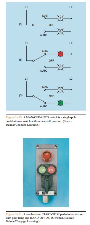
Functions Of Motor Control Selector Switches Electric Equipment
